Sponsors

free counters

Thursday, August 26, 2010

HOW TO WORK WITH SEMC PDA PHONES

first, basics.

SEMC created few types of PDA:

db200x+nexperia
m600,w950,w960,p1,p990

such phones have two security type - NEW and OLD.
Identify button will show security type - it will write "NEW SECURITY detected" with NEW security phones.

if is better to install PDA phone drivers and PDA flash drivers before any operation.

phone drivers:


for that you need to download phones.rar from support or from SEMC
turn on phone. in "connections manager->usb" select "normal mode".
now, attach cable.
windows will ask you for drivers, point it to corresponding folder within extracted phones.rar.
you must have "semc xxx usb modem" and "semc xxx application port" if drivers correctly installed.
now, turn phone off and detach it.


flash drivers:


power on smartphone in fw update mode.

- for p990/m600 press and hold "@" on TURNED OFF phone, then attach dcu60.
- for w950,w960,p1 press and hold "C" on TURNED OFF phone, then attach dcu60.

windows will ask you for a drivers. drivers in %setool2 dist%\drivers\Smartphone_Drivers


S1 OPEN
satio,vivaz,vivaz pro

S1 ANDROID,QUALCOMM BASED
x10,x10mini,x10mini pro

Nokia Permanent Memory..!

Here is little discription about Nokia PM file..!


PM field [1] - RF tunning

Protected pm field for phone RF tunning, callibration data
PM field [4,3] - Production SN

[4]
3=4D564834383034393300 - MVH480493

convert this hex data to ascii and cut null char.

4D = M
56 = V
48 = H
34 = 4
38 = 8
30 = 0
34 = 4
39 = 9
33 = 3

PM field [4,4] - Product code.

5=3035373530363900 - 0569445
PM field [4,5] - Basic production code

3035373530363900 - 0575069
PM field [4,6] - Module code

6=3032303431393700 - 0204197
PM field [4,9] - HardWare ID

9=3330303000 - 3000
PM field [4,18] - Phone oryginal IMEI

18=33353135343130343035323331393100555555555555555 55555555555555555555555555555555555555555555555555 55555555555555555555555555555555555555555555555555 5555555555555

351541040523191 - 55 55 55 are useless, when convert to ascii its UUU and two 00 are null char.
PM [58, 59, 60, 61] - Phonebook contacts, old saved contacts will be in PM 58 and recently added contacts will be saved to rest fields.
if PM 58 has 250 entires mean it has 250 contacts stored.
PM [88,0] - life timer is stored here

PM field [120] - Phone SIMLock data and SIMLock data key are stored here
PM [239] - Phone MCU version, MCU release date, and all other details are stored here

[239]
1=0D001D52303478524D343431303130303931323031303930 30303030312E584608001A00000000000000002F0000520478 09000000010CD907010009020900AC00080030003315450104 251319FFFFFFFFFFFFFFFF00000070760100010001562031302E31300A31382D31312D30390A524D2D3434330A286329204E6F6B696120003A

2031302E31300A31382D31312D30390A - ' 10.10.18-11-09' and 524D2D3434330A286329204E6F6B6961 - RM-443.(c) Nokia
PM [302] - MMC lock code
PM [308,1] - Old BB5 Phone SIMLock, Superdongel, MCU, DSP signatures and phone code in newer rapido phone!
PM [308,5] - Phone security code, old one :d

32323232320000000000 - 22222
PM [309] - battery callibration

PM field [355,1] - Dynamic camera configratoin - back Camera

[355]
1=00000014000007EC4E494D4D4949494952524646304130323130303100000000000000000000000007D80C11303032003030370000000000000000013FFFFFFF3FFFFFFF3FFFFFFF3FFFFFFF 3FFFFFFF3FFFFFFF3FFFFFFF3FFFFFFF3FFFFFFF3FFFFFFF00 0000000000000000000000000000003FFFFFFF3FFFFFFF3FFF FFFF3FFFFFFF3FFFFFFF3FFFFFFF3FFFFFFF3FFFFFFF3FFFFF FF3FFFFFFF3FFFFFFF3FFFFFFF3

4E494D4D4949494952524646304130323130303100000000000000000000000007D80C1130303200303037 - NIMMIIIIRRFF0A021001_002007

4E = M
49 = I
4D = M

And.... just convert them and you will get DCC file name and version.
PM field [355,0] - Dynamic camera configratoin - front Camera
In DCT4 phone PM fields are almost same. Just some fields are change.

3110c MMC Good Solution 100% Tested & Easy


Nokia 6500c_7900 light solution


3110C,7500 not charging 100% tested


Power Consumption and Operating Mode Phone

Power Consumption and Operating Mode

Phone status (Mode) is different: Power-Off Mode, Sleep Mode and Active Mode.
Power Off Mode, the status of this phone in a state of inactive (dead), Power (VBAT / Battery Voltage) are given to retu, TAHVO, PA, HWA Camera, Bluetooth, AHNE. Current consumption is used to 200uAmper.

Sleep Mode, this status, phone alive but is not operating. The phone will go to the Sleep Mode after 50-10 seconds if it is not used or operated. The phone will come out of Sleep Mode and go to Active Mode konsisi instrupsi if there are some, such as: connections Charger, Key press (keypad), connect the headset, phone / sms entry, etc..

In Sleep Mode, MCU and DSP are contained in the RAP is in Stand by mode. Sleep is controlled by the RAP. When SLEEPX issued a low signal which was then detected by retu and TAHVO, then the phone goes to sleep mode conditions. In this condition vCore under conditions of low (1.2 V) decreased by approximately 0.2 volts, while the FiO and fixed VDRAM 1.8Volt. VR1 is the voltage provided to VCTXO will be very low, because in this mode clock 38.4MHz System will not be generated by VCTXO. As a reference to the need Baseband Clock, Clock will be provided by the Sleep Clock oscilator that can produce 32.768 kHz.
If SLEEPX = 1 (High) and detected by retu TAHVO, it will enter Active mode conditions. All functions are enabled, VR1 to VCTXO will be active (2.5Volt) vCore also will lead to 1.4 Volt.
Current consumption required in Sleep Mode condition is very low, around 20mAmper only, while in the Active Mode conditions will need to 200mAmper current consumption, even more than that if the phone is in Burst Reception, Burs Transmission, also DSP work, etc.. One konsisi (Sub-State) in the Active Mode is the FM Radio, because retu, TAHVO and FM Radio live. FM radio circuit controlled by the MCU and Clock generated in the RAP. VR1 would be running.

In normal operation, voltage from the baseband given Battrey of 3.6 - 4.0Volt. Battery must be capable of providing a nominal capacity until 720mAmper flow.
Baseband contains several components that control the distribution of medial (Power), the entire phone system except the PA (Power Amplyfier), which have their own point of VBAT voltage (Battery). Battery provides direct phone systems throughout the retu, TAHVO, PA, HWA Camera, Bluetooth, AHNE, LED Driver, IR Module, Vibra.
Distribution system controlled by a second voltage ASICs, called retu and TAHVO. the voltage on the Hardware The phone can be given by the two ASICs, the retu and TAHVO usually called the Energy Management. Power Up Hardware entire function can not happen if the Battery voltage is less than 3Volt.

Baseband is given from six different regulators within retu and TAHVO (vCore, VANA, Fio, Vaux, VDDRAM, and VSIM), which provides a nominal voltage and current can be shown in table 1. For voltage accessories that will be connected to a system connector, will be given voltage for 2.5Volt Fout. While for the voltage provided by TAHVO via USB VBUS for 5Volt.

MMC / Micro SD and a camera that uses HWA (Hardware Accelerator) has tersendiri.VMMC regulators, namely the working teganan for MMC, dihaslkan by N3200. while VDIGCAM, namely the working voltage for the cameras, produced by the DC-DC Converter N3300.

Retu also will provide voltage VR1 (2.5Volt), VRCP1 (4.7Volt), VRCP2 (4.7Volt), VREF (1:35 Volt) for the RF Module. AHNE also provided the voltage of VBAT (Battery).

Retu have a Real Time Clock (RTC), which is given when the voltage of the RTC Backup Battery has been released. Battery Backup RTC is Rechargeble and that too in the content by retu when the main battery or the charger has been disconnected.


CLOCK DISTRIBUTION

The main clock signal (System Clock) for Baseband generated from the Voltage Temperature Control oscilator (VCTCXO). This can produce oscilator wave 38.4MHz clock signal, which then will be forwarded to the signal via pin OSCIN AHNE. Inside AHNE reconstituted clock frequency is then given to RAPGSM via pin RFCLCKP and RFCLKN.

Clock Slicer RAPGSM has therein, for MCUPLL and DSPPLL, where the Clock is a clock signal is multiplied up to a maximum of 40MHz to 130MHz for MCU and DSP. CTSI blocks within the RAP will produce for CBUS Clock 2.4MHz and 38.4MHz for RF IC control bus. Internal PLL on RAPGSM also will generate a clock signal to others who need a clock, say: MMC, SIM, CCP & I2C for the camera and Memory COMBO.


38.4MHz system clock can be stopped when the Sleep Mode, to disable the voltage to VCTCXO (VR1) generated by the retu. VCTXO can be enabled or be disabled by the control signal SLEEPX.

Sleep Clock 32.768KHz retu provides for the use of an internal clock of the RAP, where the status of the Sleep Mode, the System Clock in a state of inactivity, so instead 32.768KHz Sleep Clock Internal Clock that will give to the RAP.


SMPS Clock Clock 2.4MHz is the path of RAPGSM to TAHVO used to singkronisasi on Mode regulator is switched on. Sleep Mode In the circumstances, VCTCXO will be inactive (Off), this signal will start at the status? 0?.

Bluetooth also needs to be befungsi Clock, Clock Signal was given AHNE at 38.4MHz


TAHVO can provide 600KHz Clock, clock source is provided from the internal RC oscilator in TAHVO. 600KHz clock normally used for SMPS vCore APE, but in Nokia phones that use RAPGSM, did not have APE SMPS vCore, then the clock will not be used.

POWER UP RESET
Power up and reset the control by the retu and TAHVO. phone can live in the following manner:
Hitting the Switch On / Off, which is referred Grounding pin PWRONX of retu.
Connection to the input Charge Cell Phone Charger
RTC Alarm, RTC has been programmed to give alarm

After receiving one of these signals, retu began to enter the Reset Mode. Then the watchdog starts counting (Active), and if the battery voltage and the BSI have been appropriate then retu will launch delay (Delay) 200us. At the same time, signals from the retu RSTX will be given to TAHVO to mengaktifkanTAHVO. After the delay time has elapsed, the voltage will issue retu: VANA, Fio, VR1 and VDRAM. While TAHVO will issue teganan vCore. Then point PURX (Power Up Reset) determines low for 16ms. Reset it, then give to RAPGSM PURX to reset the MCU and DSP. During the reset phase, the command to the regulator retu VCTCXO describe without seeing the status of the control signal input to retu sleep.

POWER UP WITH BUTTON POWER

When the power button is pressed, retu and TAHVO enters a power-up sequence. By pressing the power button will make the pins in the retu taxable PWRONX Ground. Signal PWRONX not part of the keypad matrix. Only connected to the power button retu. Means that when pressing the power button, making the resulting RAP commands to turn on the MCU. MCU then reads the command register and then send a message retu PWRONX command. Then the MCU reads the status signal from PWRONX with Control BUS (CBUS). If the signal PWRONX remain low for a certain time then the power MCU considers this a valid command (right) in the system and proceed with the initialization of the Baseband Software. If the power button is indicated as not valid then the MCU power off the system baseband back.
POWER UP WHEN Charger connected

Where to be able to detect or start charging where the main batre be true? was not in charge (empty) and therefore does not have TAHVO suply (NO_SUPPLY or retu backup mode) charging in control by START-UP charging circuitry.


VBAT detected below the level where the master reset (Vmstr-) charging in control by START_UP charge circuitry. Connecting the charger to increase detection VCHAR input charger, VCHdet + by the detection of star-up kemuadian start charging. TAHVO produce 100mA fixed output flows from the charger output voltage connection. As batre in his charge, the voltage rises, and when the VBAT voltage level higher than the limit of a master reset (Vmstr +) charge in hetikan START_UP.


Monitor the voltage level of VBAT has been completed by the charge control block (Chacon). MSTRX =? 1? reset output signal (internal to UEM) is given to TAHVO RESET block when VBAT> Vmstr + and UEM in the first reset.


If VBAT is detected when it falls below Vmstr-charging start-up, charging at the stop. Will restart if new input rises above the limit VCHAR detected (rising above VCHAR VCHDET +).
POWER UP WHEN THE BATTERY connected


Baseband can live with the battery connections with enough voltage. When the battery voltage detected TAHVO retu and will enter the reset phase


The phone will be active in? LOCAL MODE? BSI resistor setting 3.3kOhm
The phone will be active in? TEST MODE? BSI resistor setting 6.8Ohm


This mode is often needed when the process of programming (Flashing).

RTC ALARM POWER UP
If the phone is in POWER_OFF mode occurs when the RTC alarm wake up procedures. After the baseband in order to give life to the MCU. When the RTC alarm occurs in ACTIVE mode command to result in the MCU.

POWER OFF
Baseband will be disabled if all conditions have been properly
? Key power in the press
? Voltage battery is too low (VBATT = 3.2 V)
Turn off the power at the control procedures by retu.

BB5 component functions

BB5 component functions

1.Level Shifter
Manage IC functions to the data path from the front camera to the CPU. When broken, will result in disruption of the function of the front camera so can not be activated.

2.64 Mbit NOR Flash
Is subuah IC with a capacity of 64 Mbit Flash. Flash IC storing programs to be executed by the CPU. There are two Flash IC damage, damage to hardware, and software. Hardware damage is damage to the IC itself, the damage occurs when the contents of a software program erased or changed by accident. Both this damage does not normally produce mobile phones, such as the total dead cell phone, hangs, LCD blank, no signal, locked phones, and many more.
How to repair, if there is damage to software is to make the process of flashing.

3.IC TK65600B
This IC is the IC to raise the DC voltage level. When the IC is damaged, could cause the lights on the screen or mobile phone keypad is not lit.

4.RAP 3G
Abbreviations of Radio Application Processor. Was one of two CPUs on BB5 phones. CPU is certainly a function of controlling the performance of the cell phone, but one of its main functions is to control, process data from cell phone radio section. When the CPU is damaged, or part of the CPU is damaged, the total mobile phone can die, no signal, and others.

5.OMAP
Stands for Open Multimedia Application Platform. Is the second CPU of a BB5 generation mobile phone. OMAP is also often called APE (Application Phone Engine). CPU function is different from the RAP 3G. This CPU is more focused on the work of existing applications such as cameras in cell phones, bluetooth, LCD, Keypad, MMC, and others. So if the CPU is problematic, or part of the CPU is damaged, will cause the death total, the keypad can not be suppressed, Bluetooth error, MMC problem, the camera is not working, LCD blank, and other

6.64 Mbit SDRAM
RAM stands for Random Access Memory, is a CPU working memory are temporary and can not store data permanently, if the working voltage of the RAM is lost, along with the data in RAM is lost even participate. When RAM is damaged, usually the total dead cell phone, can not re-programmed.

7.RETU
This IC is one of the two existing power IC in the mobile type of BB5. Damage to the IC die may cause the total mobile phone, can not find the network, no network, can not read the card, can not read MMC, interference in the audio, and others.

8.Combo Memory
This memory type is a combination of Flash with 256 Mbit 256 Mbit RAM. This memory has a capacity large enough. The contents of this memory is to store the data in the form of a program to run OMAP CPU. Not normally the contents of program memory on this combo will cause lots of damage. One of the most common is the LCD blank.

32 Khz crystal 9.Osilator
This component is a type of crystal oscillators that function to produce a single wave with a frequency of 32 768 Hz. If this component is not normally a problem could lead to mobile phones, such as mobile phones can not be lit, the problem with the clock cell phone, etc.

Static 10.Anti
Anti-static function to protect the IC from static electricity this time is used to protect the CPU from static electricity that may be entered via the keypad connector. So when the IC is damaged can cause malfunction of the keypad, or often also called? Pad hank?

11.Rangkaian LM 2708
Combination of this IC to form a series of SMPS (Switch Mode Power Supply). Or circuit switching power supply with the system. This circuit produces a voltage of 1.4 volts which is called the vCore A. This stress is working for OMAP CPU. So if there is a problem on this circuit, OMAP is not working normally, handphnone will die totally.

WCDMA antenna 12.Konektor
N70 BB5 mobile phone such as mobile phones have two systems, GSM and WCDMA. WCDMA antenna connector is dirty or bad if the connect will cause signal interference on WCDMA network.

WCDMA switch 13.Antena
The function of this component is to separate the signal Rx (Receiver) and the signal TX (transmitter). If damaged will disrupt radio system on the WCDMA system.

14.Regulator camera
The regulator function provides a stable voltage for the front camera. Disturbances in this IC circuit and malfunction of the circuit will cause the front camera on this phone N70.

15.bundle PA and the ultimate controlling
This series serves to strengthen the transmitters band WCDMA signal. IC PA is also called the final amplifier. If this component is damaged, it will be difficult to use mobile phones to call. Or it could also cause the indicator handpone no signal at all.

16.DC/DC to flash converter
This circuit is used to set the lights flash when being photographed images. How it works is to raise the DC voltage level to a higher voltage level. When the series had problems, would interfere with the function of a flash lamp.

17.HINKU
This IC may also be called the RX processor. RX signal processing functions for both GSM and WCDMA. When the IC is damaged or not working will lead to normal handphnoe no signal, weak signal receiver, and so forth.

RX 18.Filter
This filter functions as a filter. If terjdi problems with this component, the signal receiver will be disrupted. Since this is a WCDMA filter, there will be disruption on the band WCDMA, when the filter is problematic.

19.VINKU
IC is a function to process the signal TX. This IC can process the signal TX either GSM or WCDMA. If the IC is in trouble will cause problems on the transmitter. Symptoms is difficult for mobile phones, also difficult to take the phone, can also no signal at all.

Know How BB5 SECURITY SYSTEM

BB5 SECURITY SYSTEM

1. security certificate stored at the CMT flash + RAP3G & security simlock CMT areas will also be stored in flash, and RAP3G
When a corrupted or missing NPC (nokia public certificate) or simlock data will have a contact phone retailer, or restart
it is because because of data entered into the memory had previously been through an encryption process based on the algo from NPC and simlock data.!!
so if one replaced the security authentication process to be wrong.

2. when RAP3G and NOR flash (CMT flash) mounted together (with provisions RAP3G and CMT flash from normal HP), the encryption key will be matched with at RAP3G security area on the flash and the phone will be normal.!
This exact same process on the security system platform 4 hp (DCT4 & WD2). if UEM and FLASH on the same encryption key pairs will be matched.
PROCESS:
* Encryption key will be sent to the logic system certificate who is in the OTP system. if true, then the encryption key will be lit with a normal HP.

DIFFERENCES IN SECURITY PLATFORM 4 (DCT4 & WD2) and BASE BAND 5 (BB5)
security system platform 4. logic using a metronome or delay in the voltage or can call (flip - flop logic voltage) / watchdog. so if one replaced (UEM or FLASH), so the process of security and authentication into one processor will perform calculations based on the RPL. if processors find untruth encryption key calculation she will do shutsdown system

but differ in the security system BASE BAND 5 (BB5)
flip-flop logic there is no voltage if the encryption key and flash RAP3G different / not match then the HP will not experience 30 seconds of death (watchdog), the problem lies not in place its security in the power management logic.

Understanding PROBLEM SX4 or PM AUTHOR:
SX-4 algorithm for storing decrypted process in / out in the programming of data into the phone, this protection algorithm can only be taken by dump on security RAP3 and CMT flash.
if we do read full PM (permanent memory) on BB5 illuminating the SX4 does not come to capture ..!!!!
From the above explanation we'd have to know how to repair BB5 without doing SX4 ....
BB5 repair and illuminating without the SX4 has been avaible...

Knowledge The function of UEM, UPP, FLASH, RAM


Knowledge The function of UEM, UPP, FLASH, RAM

UEM (Universal Energy Management)

UEM Description


UEM Inside there are several important roles as the Energy Management Cell Phone. Unlike Nokia DCT3, UEM is a combination of several ASICs such as: CCONT, COBBA, chaps and UI DRIVERS.

UEM stands for Universal Energy Management, in accordance with its name, UEM has some very complex functions, including:
Crystal oscillator (32 kHz)

Every phone system will be found oscilator small size which can generate pulses at 32KHz,. UEM that will provide the voltage and controlling this oscilator Crystal henceforth be forwarded to the UPP.
32 kHz RC oscillator Startup

While mobile phones in Power-down state, the RF Processor Clock can not be given to the UPP, the phone can power-up is needed for Logic System Clock to the UPP. Sleep is needed for this purpose produced by the Crystal Clock oscilator 32 kHz.
Real time clock logic

Clock, Date, Alarm Clock Logic required given by Cristal oscilator 32kHz.
Regulators Baseband & RF

UEM is given by the main battery voltage of 3.7 volts (VBATT). UEM has role as distributor voltage / regulator to all systems based on voltage needs to be required in every system.

Baseband Regulator:
§ vCore, for programming that requires voltage of about 1.0 - 1.8 Volt - 200mA to the UPP (vCore vCore DSP & MCU)
§ VANA, a voltage of 8.2 Volt - 80mA for the analog system function (Btemp, VCXO Temp)
§ FiO, giving mid 1.8 Volt - 150mA to Logic I / Os (Input / Output Logic: Level Shifter MMC, IR, IC Flash & SDRAM, Bluetooth, LCD,) and UEM Logic.
§ VFLASH1, provide the main voltage of 2.8 Volt - 70mA to IR, Bluetooth, LCD, LED drivers and voltage to the BSI.
§ VFLASH2/VAUX, a voltage of 2.8 Volt - 40mA for FM Radio and other Accesories.
§ VSIM, a voltage of 1.8 - 3.0 Volt - 25mA for SIM Cards

Regulator RF:
§ VR1, a voltage of 4.75 Volt - 10 mA to the VCP
§ VR2, a voltage of 2.78 Volts - 100 mA to: VRF_TX, MODOUTP_G_TX, MODOUTM_G_TX, MODOUTP_P_TX, MODOUTM_P_TX,
§ VR3, a voltage of 2.78 Volt - 20 mA to: VDIG, Clock Out VCTXO (OSC 26MHz)
§ VR4, a voltage of 2.78 Volt - 50 mA to: VRF_RX, VF_RX, VPAB_VLNA
§ VR5, a voltage of 2.78 Volt - 50 mA to VPLL, VLO, VPRE,
§ VR6, a voltage of 2.78 Volt - 50 mA to VRXBB
§ VR7, a voltage of 2.78 Volt - 45 mA to: VCO,
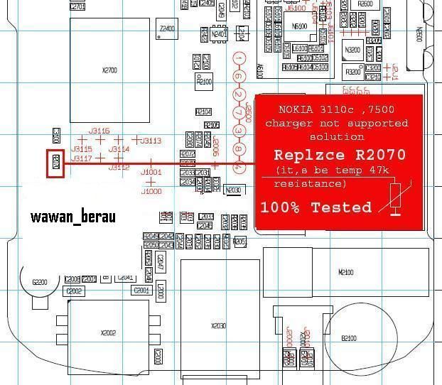
Charging functions

Cell Phone Battery charging process is controlled by the UEM. UEM has stored therein Charging Control that serves as the setting Battery charging process. The phone will automatically decide the current from the charger to Battery Battery voltage when the voltage has reached the maximum limit Charger although still connected to the phone, otherwise if the Battery voltage below the maximum voltage then the current from the charger will continue to be given to the Battery.
11-channel A / D converter (MCU controlled)

In the UEM stored 11Channels analog to digital converter used for bandgap reference and voltage reference, this section will measure the BSI, Btemp, Vcharge.
oBattery Voltage Measurement A / D Channel (Internal)
oCharger Voltage Measurement A / D Channel (Internal)
Current oCharger Measurement A / D Channel (external)
oBattery Temperature Measurement A / D Channel (external)
oBattery Size Measurement A / D Channel (external)
OLED Temperature measurement A / D Channel (external)
Interface FBUS and MBUS

FBUS & MBUS is used to transfer data from computer to phone, such as process (Flash Programming), File Manager, etc.. Those data will then be entered into the UPP and flash IC.
Security Logic (Watchdog)

Watchdog stored in UEM, first used for controlling the system power-on and power-down. Both are used to block the IMEI security and storage, Watchdog will control ROM IMEI in UEM IMEI is stored in the IC flash, if there is a difference between the IMEI in UEM IMEI and IMEI in Flash then the Watchdog will perform Power-Down within 32mS.
FLASH memory for code imei

Inside there UEM ROM used to store the IMEI data. IMEI data storage properties are OTP (One Time Programming) where the IMEI data can be written only once and can not be removed or replaced, therefore the former or never written UEM IMEI can not be used to other phones except when the IMEI is located in the IC Flash can be equated with the IMEI that is on UEM (Calulate Flash), this matter will be discussed in Chapters Software.
When the ROM was in this troubled or Corupt UEM UEM then this can not be used again and can not be repaired again, normally displays IMEI ????????? where the IMEI which is different from the UEM IMEI is supposed although there is only one number was different.
IR interface level shifters

Used to Infra red driver and the regulator, the data is subsequently forwarded to the UPP akn.
LED Interface, Buzzer and vibrator

Vibrator, Keyboad LED, LCD LED Driver UI Subsystem is controlled by residing within UEM. This driver commands to the UI provided by the UPP, UPP only give a very low voltage is required drivers to deliver enough current to the vibrator, Keyboad LED, LED LCD.
Audio codec

Earphone, Microphone, IHF Speaker, Handsfree can function as there are subsystems Audio Codec stored on UEM. This subsystem is used to modify the data signal digital information into audio signals, so that the audio signal can be heard by humans is needed strengthening (Audio Amplyfier) before forwarded to the speaker and microphone, the audio signal has a frequency of 20Hz to 20KHz.
SIM interface

SIM Card is the active component which has a microchip in it, each of which is the active component is required to supply voltage, the voltage provided by the UEM SIM Card from Baseband Regulator Subsystem 1.8 Volt - 3Volt, while the SIM Clock, Reset SIM, SIM I / O data provided through the Subsystem Interface, which has kept the SIM SIM Interface Detector, SIM and SIM IF IF Driver.
Serial control interface (Cbus & dbus Controled)

This section will control the interface using the data transmission between the UEM and UPP are implemented through CBUS and dbus to MCU Subsystem stored in the UPP.
Auxiliary A / D converted (DSP Controlled)

As a tool for konfersi analog signal into digital signal which is used for controlling DSP Subsystem stored in the UPP, this section will play a role in: Digital Speech Processing and the PDM coded audio.
RF interface converters

We have seen previously that the RF module has the character while Baseband analog signal has a digital character, so that both modules can be continuous with one another, or a translator is needed for a conversion to an analog signal into digital signal (A / D converter) and digital signal into an analog signal ( D / A converter). RF Interface Converter also called Multi Mode Converter which is a series of liaison between the RF module with UPP.


UPP (Universal Phone Processor)

UPP Description
Processor to the fourth generation Nokia (DCT4) using the UPP (Universal Phone Processor) as the center of all activities of computerization. Processor is the brain of the phone system that will work to coordinate all phone functions, including programmed instructions therein.

Nokia DCT4 technologies continue to evolve, WD2 and my heart is the development of technology DCT4. The difference is the type used Proccesor and internal memory capacity is large enough. UPP-WD2 and my heart can process data faster than the UPP DCT4, thereby facilitating features more sophisticated, such as the Symbian operating system, access the Class 10 GPRS (EDGE / BB4.5), Multi Task, TFT LCD, resolution until 2mega pixel camera, MMS, polyphonic ringtones to 48channel, MP3 player, Bluetooth, external memory (MMC Support), etc..


UPP Nokia DCT4, WD2 and my heart basically has the same structure, which distinguishes only specs: ARM, DSP Core (LEAD3) and stored in the cache RAM UPP, of course, the specification of ROM and RAM are stored in the UPP will be different from each other. UPP has several functions, including:
BRAIN

This section is the main brain of mobile microprocessor, this section has two functions:

MCU Subsystem
Subsystem MCU (Micro Controller Unit) is processed by the microprocessor ARM (Advanced RISC Machine and supported by: MCU ROM, RAM Cache, DMA (Direct Memory Acces and Memory IF.

DSP Subsystem
DSP Subsystem (Digital Signal Processing) block is processed by the LEAD (Low Power DSP Enhanced Architecture) is used to process Digital Application (A-DSP) and Digital Cellular (C-DSP). This section shall govern the data traffic information on the overall system of mobile working.

Brain Peripherals
This section will connect all the commands from the MCU and DSP subsystem to the Body.

MCU and DSP subsystem performance is dependent once the cache RAM is stored in the UPP, Nokia WD2 and my heart has a large RAM cache, about 8-16Mbit. Cache RAM is a support unit. All orders are often used by the UPP will be stored temporarily in this section. With the Cache RAM, UPP no longer need to call the same command to other parts. Thus, the time required to perform important commands can be shortened, so that speed of execution will be better and faster.
BODY

All phones work the whole system is controlled by the microprocessor. Body is part of a microprocessor that functions as the executor of orders from the Brain. Body parts functioning as Digital Control Logic also like the following:
Function
Information
ACCIF

Interface for data transfer from accessories: eg from infrared and cable Fbus / Mbus which is connected to a computer to transfer data from phone to computer.
SIMIF

SIM Card Interface. The reading of data from such sim card SIM ID, storing the SMS and Phone Book, etc..
UIF

1. Interface audio signal to the earphone and microphone
2. As an interface LCD and Keyboard Interface
3. also used for camera Codec
Pup

Software used for data transfer to external MCU and DSP are stored in external memory (Flash IC) through a connection Fbus or Mbus. Suppose the phone in Flash, then the data from the computer that is connected to the phone Fbus Block pup will be received by mobile phone from the microprocessor and flash will be stored in the IC.
CTSI

This section is used for Clock Management for: PURX, clocking, timing, Sleep Clock, etc..
SCU

Control IF / RFbus to the RF Module. This section is used to control the frequency band which will be locked to the Base Station by RF Module (PLL).
MFI, GPRS CIP, RXModem

These three blocks together is used to receive and give information to the RF data module, but previously required konfersi D / A - A / D. This section also determines the speed of data transfer, eg for access or GPRS can also be used as a modem.

UPP can work if you have been given the voltage of 1.5V which is given by the Regulator and vCore voltage Logic (FiO) 1.8 volt dibeikan by UEM. At initial boot process, UPP requires registration 32KHz Clock (Sleep Mode), while the main Clock provided by VCTCXO from RF Processor for 13MHz.

Memories (Flash & RAM)

Memories (Flash & RAM)
UPP will not be able to function fully when not assisted by the memory. As discussed previously that the UPP has MCU and DSP subsystem therein. However, the subsystem can not keep the OS (Operating System) intact, due to very limited storage data, then the extra memory needed to store the MCU and DSP Software (Firmware). Memory required by the UPP is: Flash Memory, EEPROM, RAM.

On your Nokia DCT4, Flash Memory and RAM are combined one IC, referred to as "IC Combo Flash".


Flash Memory
Flash Memory is used for data storage software MCU (Micro Controlled Unit and software DSP (Digital Signal Processor) which is an OS (Operating System) on the phone, usually called (loosely), the Flash Memory be instrumental in whether or not a phone system. Language packs or language preference (on a Nokia mobile phone called the PPM), which is stored in Flash Memory, the phone that do not have a choice of Indonesian can be added or upgraded (Re-Flash) using tools and special programs.

These data not only data stored on the operating system alone, there are also pack the data content or User Data Area is used for storing data or programs by mobile users, including: Phone Book, SMS, Games, Applications, Wallpapers, Ringtones, Images , Movie, Etc.. Flash Memory in this sector can be removed with a manual from the cell phone.

Nokia DCT4 been emulated EEPROM with Flash IC. EEPROM is used for storing important data that have been set by the phone manufacturer itself, the data contained in the EEPROM are: Signal Value tunning, IMEI / ISN, SID, MIN, SP-Lock, Security Code, etc.. Therefore, when the phone is replaced IC flashnya will require the calculation of the IMEI code, if not then the phone will not work.

Nokia DCT4 average have data on the Flash memory capacity from 16Mbit to 64Mbit. While Flash Memory on Nokia WD2 will require data storage capacity is very large, ranging from 128Mbit to 256Mbit, therefore Nokia WD2 will have two to four fruits Flash IC inside.


Flash Memory on Nokia phones that use the processor in my heart, used two separate IC Flash: First, NOR Flash, used to store primary data, this is where the MCU and Security Software IMEI is stored. Both NAND Flash, mostly used to store user data, such as: Sounds, Games, Applications, and also which stores the language packs.


RAM (Random Access Memory)
As a temporary data storage is required RAM, Nokia DCT4 still use SRAM (Synchronous RAM) with a capacity of about 64Mbit who has been in intergrasikan with IC Flash (Flash Combo), while for the Nokia WD2 and my heart to use SDRAM (Synchronous Dynamic RAM) that have a data capacity of 128-256Mbit separately from the Flash IC.

SRAM or SDRAM given supply voltage by the UEM through FiO 1.8 Volt.

how important measuring tool

Why should be measured?
Digital Electronics is a series of mobile phones which are very complex, if there is one series that does not work, then the phone can not be used properly. Although there is only one kind of stress does not exist, can cause symptoms that are fateful. The problem, in a phone machine there are tens or even hundreds of components to be interlinked with each other, of course, to solve the problem, we need to track and locate where is the problem, so that we can convict the components we need to change accordingly.

To localize the problem in the range of phones, it may take action measurement. The goal is to find work or not work a component. Basically a series of mobile phones is an interrelated system. System consists of several blocks of circuits that influence each other.

Actions measurement requires measuring instruments in accordance with elektornis elements which we will measure. Through this measure, we can know the condition of the system circuit, whether he works or not. One Indicator whether or not the circuit works by measuring the input and output.

So many support tools that a technician must be owned by Professional mobile phone, even this point extraordinary. For measurement tools only (measurement tool at least have to prepare the Budget of about 2000 - 4000 us dollar. But in this book, I try to present the effectiveness and efficiency of analyzing a technician to maximize support tool that is affordable.

Obviously we are very aware, without adequate measuring tool we can not detect the problem accurately, but that does not mean if you do not have all the tools do not support a technician can take corrective action. What is clear for a technician is required to apply creative and innovative in using existing equipment. The problem now is why in analyzing the damage to the phone we must do the measurement? And what measuring tool able to accurately provide guidance in analyzing the damage to your phone with an affordable price?
Let us look at the answer.

Does AVO-Meter is enough?
Not a few phone technicians today think that even just using the AVO-Meter just had had enough for use as measure of damage to detect the phone. In fact, as the meaning of the AVO-Meter is Amperes, Volts, Ohms Meter. It's certainly impossible to know the all the elements of an electronic device, for AVO meters only understand voltage value, the value of current consumption, as well as a series resistance value. While the phone is not an analog electronic devices, but almost 70% of digital system already works. Mobile electronic elements include: Voltage and Current Electric, Digital Data, Clock, Frequency, and others.

what measuring tool able to accurately provide guidance in
analyze the damage to your phone with an affordable price?

Ideally, measuring equipment for mobile phones is a tool measuring machine that can recognize the value of the analog elements and digital elements. Therefore, a series of measurement tools for mobile machines require special tools and advanced. However, these tools not only to its price value, but also difficult to obtain, except by certain circles who received support from mobile phone vendors.

Therefore, we need to maximize the common measurement tool and affordable but can help in analyzing the maximum. To be able to maximize the tool should we claimed to be more creative in using existing facilities on the instruments.
Efficiency measurement can be concentrated to the actions in measuring the values common to electronic circuit, such as resistance, voltage, voltage control, current consumption, clock, radio frequency, and shape data.

Flashing with UFS HWK Samsung

A little info on how to repair / flashing with UFS HWK Samsung by me

- Select the appropriate cable.
- For flashing, do not use the battery (although there are some who have to use batterie
- To its best use batteries info
- For death and total ..please flash MCU and CTS / FS
- To Hang / her good restart flash FS / CTS its course
- An important "do not forget to check the format of FS at each flashing".
- If phone can at his usual info already in the normal condition, if phone in the dead but could at info check batere, flexible (other HW parts of it)
- To be able to switch on the hp info (rev not installed), new info click pairs of wires.
- It can be used to restart the info, but for ordinary Hang her could not diinfo.
- Click to open Phonelock enough info, if successfully read info then it will be read lock code, if it fails please click unlock.
- For example the Indonesian language DX Flash File code, eg M620DXHE3

Nokia BB5 Off Line New Solution 2010


Download

Stay Connected